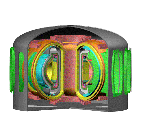
Figure 1. ARIES-RS fusion power core
Fusion Energy Research Program, University of California, San Diego
La Jolla, CA 92093-0417
(note, the full poster is also available here)
The ARIES-RS tokamak power plant is based on the reversed-shear plasma mode of operation and uses vanadium alloy as the high-temperature structural material and Li as the coolant. The design process emphasized the attainment of the top-level mission requirements developed in the early part of the study in a collaborative effort between the ARIES Team and representatives from U.S. electric utilities and industry. Major efforts were devoted to develop a credible configuration which allows rapid removal of full sectors followed by disassembly in the hot cells during plant operation. This was adopted as the only practical means to meet availability goals. Use of an electrically insulating coating for the self-cooled blanket and divertor provides a wide design window and simplified design. Optimization of the shield, which is one of the larger cost items, significantly reduced the power core cost by using ferritic steel where the power density and radiation levels are low. An additional savings is made by radial segmentation of the blanket, such that large segments can be reused. Design features and critical issues for the first wall, blanket, divertor, heating and current drive, and magnet systems are summarized.
The overall tokamak configuration is described here briefly, together with each of the major power core components: the first-wall, blanket and shield; diver-tor; heating and current drive; and magnet systems. A brief summary of the design features and operating characteristics is given, and the principal conclusions summarized.
| Major radius | 5.52 m |
| Minor radius | 1.38 m |
| Elongation (x-point) | 1.9 |
| Plasma current | 11.3 MA |
| Bootstrap current fraction | 0.88 |
| Toroidal field on axis | 8.0 T |
| Toroidal beta | 5.0 % |
| Average neutron wall load | 4.0 MW/m2 |
| Fusion power | 2167 MW |
| Gross electric power | 1204 MW |
| Net electric power | 1000 MW |
| Gross cycle efficiency | 46 % |
Figure 1 shows a cutaway view of the fusion power core. The plant availability goal was a primary influence on the overall configuration.
The vacuum vessel is a double-walled steel struc-ture with reinforcing ribs that closely surrounds the shield. A "bell jar" cryostat was chosen over the close-fitting design adopted in earlier ARIES studies to simplify the configuration. Horizontal mainten-ance of full sectors is performed through large ports using transporter casks [2]. Port doors on the back of the shield and at the cryostat prevent the spread of radioactive contamination to the confinement build-ing. All coolant connections are made in the evac-uated port area where the radiation field is low. This design allows rapid disconnections of the piping, which could be either mechanically sealed or cut and rewelded.
Figure 1. ARIES-RS fusion power core
One of the distinctive features of this design is the integration of the sectors. The first wall, blanket, parts of the shield, divertor and stability shells form an integral unit within each sector. These "replacement units" are shown in Figure 2. The integrated sector construction eliminates in-vessel maintenance operations and provides a very sturdy continuous structure able to withstand large loads. Gravity loads are supported at the bottom through the vacuum vessel. Sectors are disassembled and reuseable parts maintained in hot cells after the plant returns to operation. No rewelding is needed for elements located within the radiation environment.
The most severe penalty of single-piece sectors is the increased size of both the TF and PF coil systems, needed to allow adequate space for sector removal. With an optimized design, the cost of the increased size of the TF and PF coils is 2~3 mill/kWeh, which is substantially smaller than the cost savings due to the increased availability.
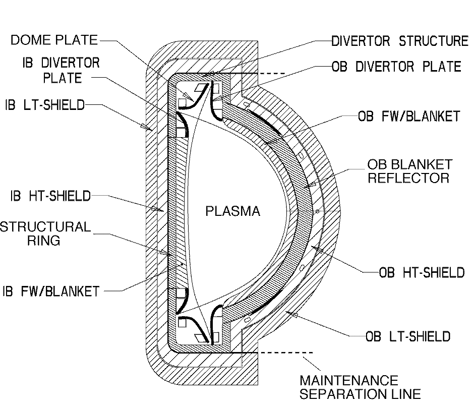
Figure 2. Sector elevation view
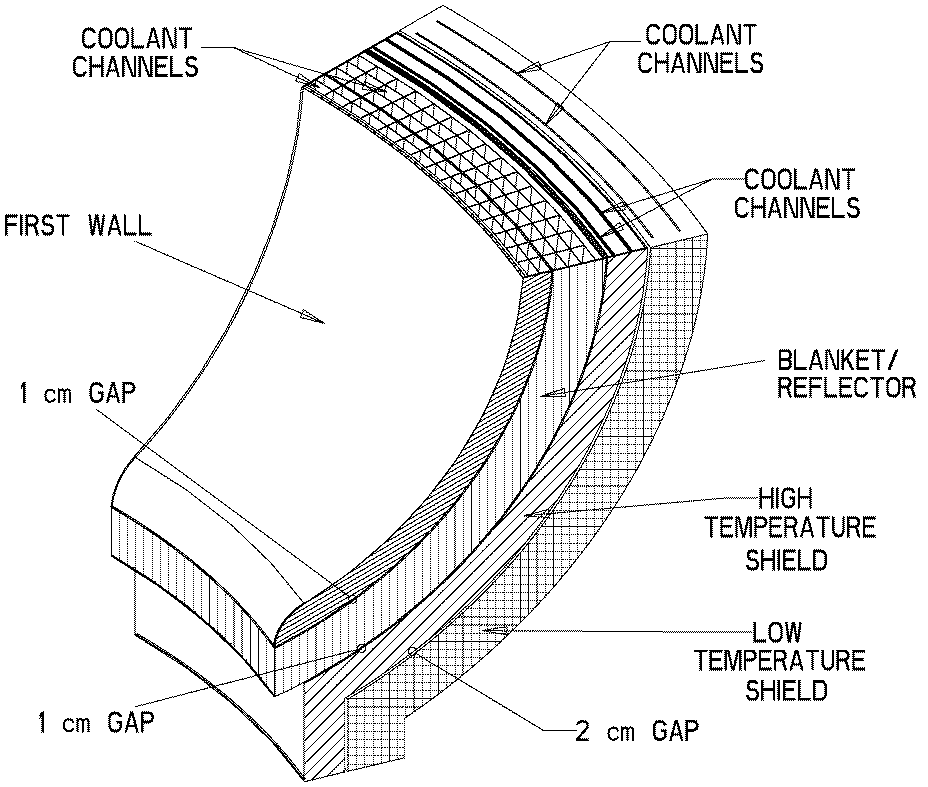
Figure 3. Outboard blanket and shield
An important feature of the blanket and shield is the radial segmentation into four zones: two blanket zones and two shield zones. The blanket is divided into two regions to maximize the lifetime of the structures, reduce the replacement cost, and minimize the waste stream. Scheduled replacement occurs after 2.5 full power years (FPY), or when the V-alloy reaches 200 dpa. At that time, the front portion is disposed, but the rear portion can be used until it reaches its own useful life, at about 7.5 FPY. The rear portion also serves as the structural ring, which provides poloidal continuity to the sectors and attachment points for the inner blanket segments. Location of the coolant connections outside the vacuum vessel allows for easy disassembly of the segments. Radial segmentation creates safety con-cerns, since radial heat transport pathways are critical in loss-of-coolant scenarios. Design solutions have been proposed; however blanket response to coolant loss remains an important concern.
Table 2 summarizes the heat loads and peak temperatures in the blanket and divertor. Multiple flow passes in the blanket provide the capability for removing at least 0.5 MW/m2 of surface heat flux, which may be necessary with a highly-radiative divertor mode of operation. The full coolant flow is passed first through the front zone, where the surface heat flux creates large temperature gradients, and then through the back zones where the bulk temperature can be raised by volumetric heating without exceeding any structure temperature limits. Segmentation of the shield into a hot and cold zone allows partial utilization of the heat deposited, and also provides further capability for superheating the coolant away from the high heat flux region.
| Multiplied neutron heating | 2092 MW |
| Total transport power | 431 MW |
| Bremstrallung power | 56 MW |
| Core line radiation | 25 MW |
| Power reradiated in divertor | 341 MW |
| First wall surface heating | 165 MW |
| Divertor total surface heating | 348 MW |
| Divertor particle power | 88 MW |
| Blanket bulk outlet temperature | 610 deg C |
| Divertor bulk outlet temperature | 610 deg C |
| Peak V temperature in first wall | ~700 deg C |
| Peak V temperature in divertor | 681 deg C |
An advanced Rankine cycle conservatively offers 46% gross thermal conversion efficiency. High thermal efficiency is desirable to partially offset the high capital cost of fusion. A double-walled IHX with a Na secondary loop is used to isolate the activated Li primary coolant from the steam side. The IHX is also the location where the transition from V to SS is made. The piping which connects the blanket to the IHX uses a double-walled structure with a thin V liner to minimize the added cost of vanadium.
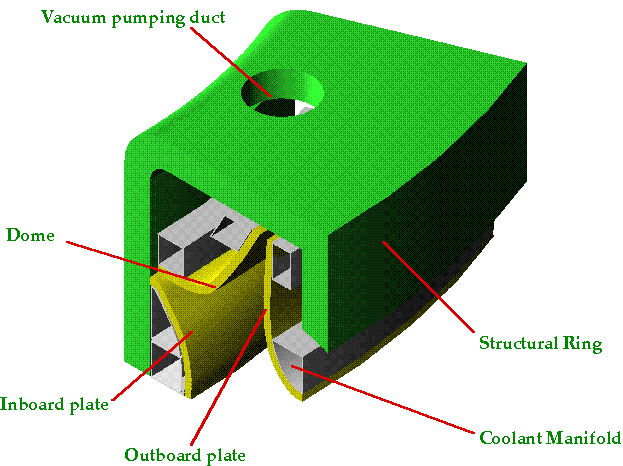
Figure 4. Divertor geometry
The target plates include three pieces: inboard, outboard, and "dome" plates. The plasma flows through the scrape-off layer and enters the divertor, where enhanced line radiation from injected neon impurity allows much of the power to be distributed along the plates and also partially redirected out to the first wall. Most of the unradiated particle energy strikes the outboard plates, but the peak heat flux has been maintained below 6 MW/m2. The strike points are located close to the coolant inlet in order to maintain the vanadium structures below 700 deg C.
The target plates are shown in Figure 5. A 2-mm thick catellated W coating is applied to the coolant channel front surface, which is only 1-mm thick V to satisfy temperature limits. Thermal stresses are reduced by using a relatively thick solid back on the target plates. The plates are connected to the rear zone via strong adjustable screw-type attachments. These attachments can be designed to react the full force of disruptions and also accommodate thermal expansion. They also permit precise alignment to adjacent surfaces and removal of individual plates in the hot cells.
Vacuum pumping ducts are placed behind the dome near the strike points for efficient exhaust. Radial channels then direct the gas to a single set of cryopumps at the bottom of the machine. Top-to-bottom conductance connecting both divertors is achieved by using the inter-sector vessel volume underneath TF coils.
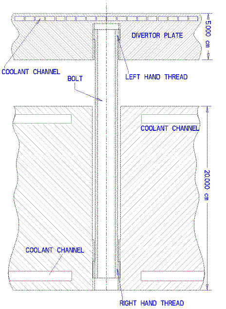
Figure 5. Divertor plate and attachment
Folded waveguides (see Figure 6) were chosen for the ICRF system as the most compact, robust mech-anical structures. Thin copper coatings on all wave-guides are used to minimize the dissipated losses.
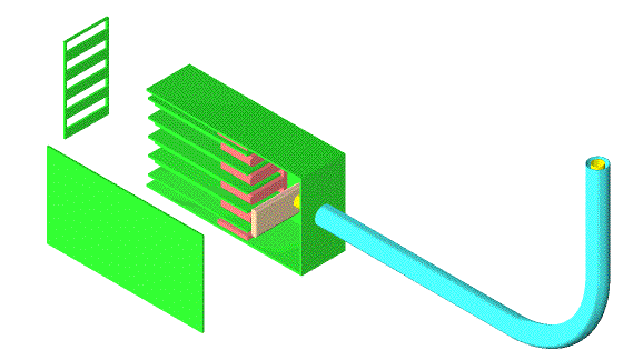
Figure 6. ICRF folded waveguide launcher
Support of out-of-plane loads has been provided without intercoil structure in the outer legs of the TF coils, using caps and outer straps. This makes full-sector maintenance possible. The cap and strap structures also have been shown to accommodate off-normal events (e.g., a single coil short during a dump) and the bending stresses due to the shaping.
The PF coil set consists of 24 coils: 10 form the center stack, and the remaining 14 elongate the plasma, provide equilibrium and form the divertor magnetic configuration. An attempt has been made to keep the field at the PF coils <8 T, such that less expensive NbTi conductors can be used. This is accomplished by shaping the TF coils and by allow-ing a larger number of closely-spaced PF coils.
1. F. Najmabadi and the ARIES Team, "The Starlite Project: The Mission of the Fusion Demo", 16th IEEE Symposium on Fusion Engineering, Sept 30.-Oct. 5, 1995, Champaign IL.
2. L. M. Waganer, V. D. Lee, and the ARIES Team, Designing a Maintainable Tokamak Power Plant, these proceedings.
3. Private communication, D. K. Sze, Argonne Nantional Laboratory.
* Work supported by the US Department of Energy
** Institutions participating in the ARIES Team, in addition to UC San Diego, include Argonne National Laboratory, General Atomics, Los Alamos National Laboratory, Massachusetts Institute of Technology, McDonnell Douglas Aerospace Co., Princeton Plasma Physics Laboratory, Raytheon Engineers and Constructors, Rensselaer Polytechnic Institute, and the University of Wisconsin-Madison.