(*Work supported by U.S. DOE Contract No. DE-AC02-76-CHO3073)
Abstract -- The ARIES team is presently assessing the feasibility of a low aspect ratio (LAR) or spherical tokamak (ST) to serve as a commercial power plant. Development of a credible design for the centerpost is one of the key feasibility issues. In this paper, centerpost design options are identified and systematically assessed.
A. Magnet System Design Point
A "strawman" design was developed for earlier work on spherical tokamaks. Subsequent to establishing this "strawman", there were two developments which favored not using this strawman for evaluating the centerpost (CP) design options:
On the basis of these findings, a higher aspect ratio design point with a modestly smaller major radius was identified for the purpose of evaluating CP design options. Parameters for the magnet study design point are listed in Table I. Two variants of the magnet design study point are shown: one with a 20 cm shield envelope and one with a 30cm shield envelope. One of the design constraints is that the CP must be disposable as Class C waste. A 15-20 cm shield restricts the lifetime of the CP to approximately the same lifetime as the plasma facing structures, 10-15 MW-y/m2. A thicker shield would reduce the frequency at which the CP would have to be replaced due to its waste disposal rating (WDR).
By increasing the aspect ratio from 1.25 to 1.5, the radius of the centerpost can be increased by 0.5m while decreasing the major radius by the same amount. Decreasing the shield envelope from 30 cm to 20 cm allows a corresponding increase in the radius of the CP. However, the power which has to be removed from the CP in the 20 cm and 30 cm options is nearly the same. The decrease in Joule dissipation in the larger radius CP is nearly offset by the increase in nuclear heating due to the thinner shield.
Table I
Parameters for Magnet Study Design Point
| Parameter | Units | 3/96 Strawman | 20cm Shield | 30cm Shield |
| R | m | 5 | 4.5 | 4.5 |
| a | m | 4 | 3 | 3 |
| A | 1.25 | 1.5 | 1.5 | |
| k95 | 3.0 | 3.3 | 3.3 | |
| d95 | 0.45 | 0.56 | 0.56 | |
| Bt | T | 1.77 | 1.81 | 1.81 |
| It | MAT | 44.3 | 40.7 | 40.7 |
| Ip | MA | 40.1 | 33.9 | 33.9 |
| It/ Ip | 1.1 | 1.2 | 1.2 | |
| bn | % | 6.4 | 7.4 | 7.4 |
| fbs | % | 100 | 99 | 99 |
| Pf | MW | 4530 | 4500 | 4500 |
| Q | &infty; | 40 | 40 | |
| Dshield-plasma | m | 0.134 | 0.134 | 0.134
|
| [Delta] shield | m | 0.300 | 0.200 | 0.300 |
| rCP | m | 0.566 | 1.166 | 1.066 |
| hCP | m | 34 | 28 | |
| JCP,ideal | MA/m2 | 44 | 9.5 | 11 |
| PCP,[Omega] | MW | 1438 | 312 | 379 |
| PCP,nuc | MW | 112 | 60 | |
| PCP,tot | MW | 424 | 439 |
B. Configuration
The choice of a single turn or multi-turn CP is among the most critical choices to be made. A single turn coil refers to a configuration in which all of turns are electrically in parallel with current sharing between turns. This configuration has some marked advantages:
The need to electrically isolate the one end of the CP from the outer TF legs favors a design in which the CP and outer TF legs are not rigidly coupled, resulting in lower axial forces in the CP.
A multi-turn configuration also has advantages:
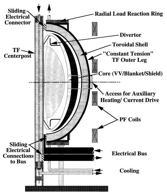
A configuration concept for a single turn coil system is illustrated in Fig. 1. The configuration features a CP which is located outside the plasma vacuum boundary behind a thin shield. The CP is physically separate from the core (vacuum vessel, shield, and first wall) assembly. If the centerpost is cylindrical, it can be replaced without disturbing the vacuum vessel or TF outer legs. Shaping the CP to reduce Joule losses would "trap" the CP requiring disassembly of the core for CP replacement or incorporation of the core and CP into a common assembly. The plasma configurations being considered for the ARIES-ST study are high elongated (k>3) and triangular (d>0.5). For these plasma configurations, the benefit of shaping is considered to be very small. Thus, for this study, a cylindrical CP was assumed.
The TF outer legs approximate a constant tension shape which requires a purely radial reaction at the ends. This radial reaction is provided by a toroidally continuous shell outside the TF outer legs reinforced by reaction rings near the ends. The toroidal shell should be very effective in resisting the TF overturning moment. Small ports openings in the toroidal shell are provided for plasma heating, current drive, and diagnostic access.
TF outer legs are electrically attached to the CP though sliding electrical contacts on top of the tokamak. The CP and outer legs are attached to the electrical bus at the bottom, also through sliding electrical contacts. The core assembly can be replaced as a unit by removing the CP and then horizontally moving the TF outer leg/toroidal shell segments. Numerous concepts for sliding electrical contacts have been developed, tested, and even deployed for fusion applications. These concepts include; feltmetal pads (used on C-Mod and proposed on MAST), Multilam sliding contacts [1], and spring-loaded, in-line contacts [2].
The magnet system configuration must be developed as part of the overall tokamak configuration. In the ARIES-ST studies, development of the tokamak configuration is being aggressively pursued. Numerous concepts are being explored in an effort to identify an optimal configuration.
The large conductor currents in the single turn configuration, while formidable, do not appear intractable from a power supply standpoint. A scheme for providing a very high current (multi-megamp) power supply has been developed. The scheme uses a large number of diode rectifiers connected in parallel to provide current to the TF load. One characteristic of this power supply scheme is that there will be a ~1V drop across the one layer of diode rectifiers. The consequent power dissipation in the power supply will be ~40MW. Power supply costs are expected to be modest, of the order $100/kVA.
Joule losses in the bus might be even higher. The losses in the air-cooled TF bus being designed for ITER are 0.29 W/kA-m. This translates to bus losses of ~60MW for this design point, assuming a 50m bus length.
Oxygen-free copper was commonly the conductor of choice for early,
normal-superconducting tokamaks because of its outstanding electrical and
thermal conductivity. There are other copper alloys available which provide
higher strength (especially at elevated temperatures) but with reduced
electrical and thermal conductivity. However, none of the early tokamaks needed
to be designed for a high radiation environment.
Conductor requirements for a power reactor include:
The CP, unless well shielded, will be subject to high radiation doses.
Potential radiation effects in the centerpost include void swelling,
irradiation creep, degradation of electrical and thermal conductivity,
radiation hardening, embrittlement, and activation.
Irradiation at temperatures below 150°C causes pronounced hardening in
pure copper and precipitation hardened (PH) and dispersion strengthened (DS)
copper alloys. Hardening resulting from low temperature irradiation is
accompanied by dramatic embrittlement [3]. The uniform elongation generally
decreases to less than 1% even at doses as low as 0.01 to 0.1 dpa. In contrast,
the expected dose at the centerpost will be several dpa to tens of dpa. This
phenomenon changes at higher temperatures. At temperatures greater than
150°C, CuCrZr (a PH alloy) and DS copper alloys have a satisfactory level
of ductility, with irradiated elongations in the range of 50-90% of the
unirradiated values [7].
Oxygen-free copper is unsuitable for operation at elevated temperatures due to annealing and loss of strength. Precipitation hardened alloys maintain their yield strength at elevated temperatures better than oxygen-free copper but diffusion bonding and furnace brazing generally result in unacceptable softening during fabrication. DS copper alloys such as Glidcop AL-15 appeared well-suited for operation at elevated temperature. They adequately resist creep, swelling, softening, and helium embrittlement up to high irradiation doses in the temperature range of 150°C to 350°C (or perhaps higher) [3]. DS alloys can be satisfactorily joined by brazing, explosive bonding, or diffusion bonding (hot isostatic pressing) [4]. The main concern at elevated temperatures is a loss of fracture toughness. Dramatic drops in fracture toughness at 250°C and under irradiation have been reported [5].
All copper alloys will be subject to transmutations which decrease the
electrical and thermal conductivity and elevate the waste disposal rating. The
waste disposal rating (WDR) appears to be a more critical concern [6]. Single
turn coils have the advantage over multi-turn coils in that the current in the
CP can gracefully redistribute as the resistivity increases in the plasma
facing regions.
Hoop stresses in the CP are low for the design point established for this
study. Average hoop stresses are ~5ksi in compression. If there is no rigid,
mechanical connection between the CP and TF outer legs, the axial tension in
the CP is even smaller, less than 2ksi. However, stresses are likely to be
higher in subsequent design points generated by a systems code optimization
process.
Glidcop AL-15 operating at modestly elevated temperatures (above 150°C and below 250°C) appears to be an interesting option for the CP design, perhaps skirting regimes where embrittlement and loss of fracture toughness could be problematic. At temperatures common for conventional, water-cooled coils (20-35°C inlet) and below, embrittlement of the CP appears to be a critical issue with modest shield thickness. Structural design criteria for embrittled material need to be applied. Fatigue data for irradiated AL-15 appears to be sorely lacking.
Cryogen-cooled conductors will require substantial shielding to reduce the nuclear heating. The shielding will also reduce the radiation dose to the conductor at the expense of higher TF field, higher current density and higher stresses. An assessment of the viability of cryogen-cooled conductors (oxygen-free copper and high purity aluminum) is made in the following section.
Several cooling options have been identified for evaluation:
A simple power flow model for the plant was constructed for the purpose of evaluating these options. Organic coolants, commonly used in process industries in elevated temperature applications, were not modeled because of their rapid degradation in a high radiation environment. A minimum shield thickness of 20cm was imposed based on WDR considerations. For the cryogen-cooled options, the shield thickness was chosen to minimize the heat load to the refrigerator. An increased shield thickness reduces the nuclear heating at the expense of increased Joule heating. All options are limited to an inlet pressure of 500psi. Coolant velocities are limited to 20m/s for gaseous helium and 10m/s for all other coolants.
Liquid metal cooling was first considered in the context of an integrated blanket coil (IBC). In the IBC concept, liquid lithium serves as a breeding material, a conductor, and a coolant. Calculations showed that a pure liquid lithium system is unattractive because of excessive Joule losses. These losses can be reduced by using the liquid metal as a coolant inside a copper conductor. AL-15 was assumed as the conductor material because of the need to operate at temperatures above the melting point of lithium (180°C). A thin steel sleeve is required between the lithium and the conductor because of material compatibility issues. An electrically insulating coating must be applied to the inside of the steel sleeve to reduce MHD pressure drops to manageable levels. The option may only be attractive if water cooling is not be compatible with the blanket or first wall cooling scheme. The maximum conductor temperature is necessarily high (290°C), owing to the high inlet temperature (200°C) and high temperature drops across the conductor, steel sleeve, and insulator. Radiation embrittlement should not be a concern in this temperature range but loss of fracture toughness is. Joule losses are 70% higher than in a water-cooled coil because of the higher operating temperature and higher coolant fraction. Even with optimistic assumptions for energy recovery, the higher Joule losses are only marginally offset. In addition, the engineering difficulties associated with the liquid lithium coolant are severe.
In the previous section, embrittlement due to irradiation at low temperatures (<150°C) and loss of fracture toughness due to elevated temperature and a high radiation environment (data at 250°C) were identified as radiation effects relevant to Glidcop AL-15. Water is a candidate coolant which can be used to keep the conductor well within a 150-230°C temperature range without exceeding reasonable pressures or flow velocities. Joule losses will be about 50% higher than when the conductor is cooled with ambient water. However, if the allowable stresses at low temperature are unacceptably low, the warm water option would be interesting. If the allowable stresses are acceptable, the ambient water option would be preferred.
A fourth option is to use copper operating in a temperature range appropriate for liquid nitrogen (LN2) cooling (80-110K). The resistivity of copper drops substantially from room temperature to 80K, in the ratio of approximately 7.7:1, so there is incentive for operating at lower temperatures. However, in order to minimize the heat load to the refrigerator, the shield thickness has to be increased from 20cm to 44cm. The peak TF field increases to 8.8T and the conductor current density to 2.1kA/cm2. The Joule heating in the CP drops from 300MW to 76MW, even with the smaller CP radius. The nuclear heating in the CP drops from 158MW to 35MW. Nevertheless, the net electric power drops to 423MW (far less then the nominal 1000MW for the ambient water-cooled option) because of the poor thermodynamic efficiency in removing heat at 80K, approximately 7W per watt removed.
Another option is to use copper operating in the temperature range of 30-50K using gaseous helium. The resistivity of copper drops substantially from room temperature to 30K, in the ratio of approximately 100:1, so there is incentive for operating at temperatures even lower than 80K. In order to minimize the heat load to the refrigerator, the shield thickness has to be increased to 66cm. The peak TF field increases to 11.5T and the conductor current density to 4.1kA/cm2. The Joule heating in the CP drops to 15MW. The nuclear heating in the CP drops to 9MW. Nevertheless, the net electric power is still only 388MW because of the very poor thermodynamic efficiency in removing heat at 30K, approximately 37W per watt removed.
The resistivity of copper becomes independent of temperature at temperatures below ~20K. Copper also exhibits a strong magneto-resistance. For temperatures less than 20K, the magneto-resistance for high conductivity copper (RRR>100) is dominant above 4T. Aluminum exhibits a much weaker magneto-resistance than copper which saturates with increasing field. Thus, high purity aluminum is often proposed as a conductor in very low temperature (<20K), high field applications. Using high purity aluminum conductor in the temperature range of 10-20K appears optimal based on a minimization of the product of the resistivity and the Carnot work (Wc~Th-Tc/Tc in W/W). The average resistivity (re[15K]) is assumed to be .008 mW-cm with an average field of 9.7T. This is lower than RT copper by the ratio of 215:1. The zero field resistivity for this high purity (99.999% pure) aluminum is .0009 mW-cm at 15K and has a RRR exceeding 5,000 at 4K. The high purity aluminum conductor can be cooled with gaseous helium. In order to minimize the heat load to the refrigerator, the shield thickness has to be increased to 80cm. The peak TF field increases to 14.5T and the conductor current density to 5.5kA/cm2. The Joule heating in the CP drops to 5.0MW. The nuclear heating in the CP drops to 3.8MW. Nevertheless, the net electric is still a meager 57MW because of the extremely poor thermodynamic efficiency in removing heat at 10K, approximately 119W per watt removed. The bottom line is that the cryogen-cooled options do not appear to offer any improvement over the water-cooled and Li-cooled options based on thermodynamic efficiencies for the design point used in this study.
A magnet system configuration has been developed based on a single turn CP.
Sliding joints are used to enhance maintainability and minimize the axial load
on the CP. Cylindrical or shaped centerposts can be accommodated. However, for
the highly elongated and triangular plasma shapes being considered for the
ARIES-ST study, the benefits of shaping appear small.
The leading conductor candidate is DS copper (Glidcop AL-15) operating at
ambient or elevated temperature and cooled with water. Radiation embrittlement
at low temperature (<150°C) and loss of fracture toughness due to
irradiation and elevated temperature are the primary materials concerns.
[2] Holt Murray, "High Current Density, Cryogenically Cooled Sliding Electrical Joint Development", PPPL-2370, September, 1986
[3] F.A. Fabritsiev, S.J. Zinkle, and B.N. Singh, "Evaluation of copper alloys for fusion reactor divertor and first wall components", J. Nucl. Mater. (1996) preprint
[4] S.J. Zinkle and S.A. Fabritsiev, "Final Report to US Home Team for 1994 ITER R&D Task T7: Assessment of Copper Alloys for High Heat Flux Applications"
[5] D.J. Alexander and B.G. Gieseke, "Fracture Toughness and Fatigue Crack Growth of Dispersion-Strengthened Copper", DOE/ER-0313/19, pp. 189-194
[6] L. El-Guebaly and H. Khater, ARIES Project Meeting, March 6-7, 1997
[7] S.A. Fabritsiev, A.S. Pokrovsky, S.J. Zinkle, and D.J. Edwards, "Low Temperature Embrittlement of Copper Alloys", Journal of Nuclear Materials, September, 1996